*Remember: All formulas as well as the resistor color code chart will be given. You must be able to apply the correct formulas and use the given information correctly.
Intro. to Electronics Mid-Term Kahoots
Mid-Term Review https://play.kahoot.it/#/k/4b766771-2aea-40bd-864a-f743825ee80b
Components- https://play.kahoot.it/#/k/a46259aa-f5b0-4e94-aa53-b0ee08ec17fa
Binary/Hex/Gates- https://play.kahoot.it/#/k/f7d24f27-a7fd-4a19-bad4-42551a8ad752
Energy Basics - https://play.kahoot.it/#/k/7be99015-bf18-44ef-a926-79b781ee5b07
Hex to Decimal- https://play.kahoot.it/#/k/a954beba-1a44-443b-8ba4-79216a24af0b
Binary to Decimal- https://play.kahoot.it/#/k/6feb01f1-5538-42e3-8ed5-06f9738e5800
Component Symbols- You must be able to identify the component and component symbol as well as list the basic functions of the component.
Resistor Color Chart- must be able to use correctly.

Power Formula Wheel/Ohm's Triangle
WILL BE GIVEN! JUST NEED TO APPLY THE CORRECT FORMULAS IN PRACTICE.


Ohm's Law Practice Problems
Awesome Website with Tons of Practice Problems.
Ohms Law Practice Problems #1 - Feel Free to search site for others!
Series vs. Parallel Circuits! (yes it's from wikipedia!)
Components of an electrical circuit or electronic circuit can be connected in many different ways. The two simplest of these are called series and parallel and occur very frequently. Components connected in series are connected along a single path, so the same current flows through all of the components. Components connected in parallel are connected so the same voltage is applied to each component.
A circuit composed solely of components connected in series is known as a series circuit; likewise, one connected completely in parallel is known as a parallel circuit.
In a series circuit, the current through each of the components is the same, and the voltage across the circuit is the sum of the voltages across each component. In a parallel circuit, the voltage across each of the components is the same, and the total current is the sum of the currents through each component.
Series Circuit - All current is the same throughout!


Paralell Circuit - Voltages same throughout!


Rtotal= 1/(1/R1+1/R2+1/Rn+
Capacitors in Series vs Parallel
Series 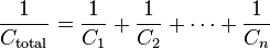 .
.
Parallel  .
.
Transistors- Either Amplify or Switch!
3 pins!
Emitter- Connects to either - or +
Base- Controls the current flow based upon a difference between it and the emitter pin. For EX: With an NPN (Negative, Positive, Negative) transistor, the Emitter pin connects to negative, and a positive charge applied to the Base pin allows a connection from the Emitter pin to the Collector Pin.
Collector- Connects to "Load"
Boolean Algebra: (Wikipedia Definition)--- Just FYI!
In mathematics and mathematical logic, Boolean algebra is the subarea of algebra in which the values of the variables are the truth values true and false, usually denoted 1 and 0 (respectively). Instead of elementary algebra where the values of the variables are numbers, and the main operations are addition and multiplication, the main operations of Boolean algebra are the conjunction and, denoted ∧, the disjunction or, denoted ∨, and the negation not, denoted ¬.
Boolean algebra was introduced in 1854 by George Boole in his book An Investigation of the Laws of Thought. According to Huntington the term "Boolean algebra" was first suggested by Sheffer in 1913.
Boolean algebra has been fundamental in the development of computer science and is yet the basis of the abstract description of digital circuits. It is also used in digital logic, computer programming, set theory, and statistics.
Basic operations
The basic operations of Boolean algebra are the following ones:
- And (conjunction), denoted x∧y (sometimes x AND y or Kxy), satisfies x∧y = 1 if x = y = 1 and x∧y = 0 otherwise.
- Or (disjunction), denoted x∨y (sometimes x OR y or Axy), satisfies x∨y = 0 if x = y = 0 and x∨y = 1 otherwise.
- Not (negation), denoted ¬x (sometimes NOT x, Nx or !x), satisfies ¬x = 0 if x = 1 and ¬x = 1 if x = 0.
If the truth values 0 and 1 are interpreted as integers, these operation may be expressed with the ordinary operations of the arithmetic:
- x∧y = xy,
- x∨y = x + y - xy,
- ¬x = 1 - x.
- Example Mid-Term Problem with Logic Gates:
Give the Boolean Equation for the gates shown above.
1. [(AB)(C+D)]NOT=Q (A line above the part within the brackets would also be acceptable in lieu of the NOT.)
2. (AB)+(CD)=Q
digital Logic:
http://www.wisc-online.com/Objects/ViewObject.aspx?ID=DIG1302
http://www.neuroproductions.be/logic-lab/
http://www.wisc-online.com/Objects/ViewObject.aspx?ID=DIG1202
http://www.wisc-online.com/Objects/ViewObject.aspx?ID=DIG2503
Gates

Useful Links:
Logic gate online simulator: http://www.course.com/downloads/computerscience/aeonline/7/1/index.html
Boolean Algebra tutorial: http://www.doc.ic.ac.uk/~dfg/hardware/HardwareLecture02.pdf
http://www.facstaff.bucknell.edu/mastascu/elessonshtml/logic/logic1.html
Things to review! - See other pages on website for more info!
- Resistor color decoding
- Types and functions of electronics components (ex.: capacitor, transistor, LED, potentiometer.. etc.)
- Calculating resistance/voltage/current using Ohm's Law
- Using Logic Gates
- Binary/Hexadecimal Conversions